Overview of the Tile Grid and Coordinate System
This page is currently under construction. Content should be added by October 7, 2020.
File Name: Boston Metro Tile Grid
Updated: July 6, 2021
Formats: Autodesk DXF, Trimble Sketchup, ESRI Shapefile, GeoJSON
Tiling Strategy
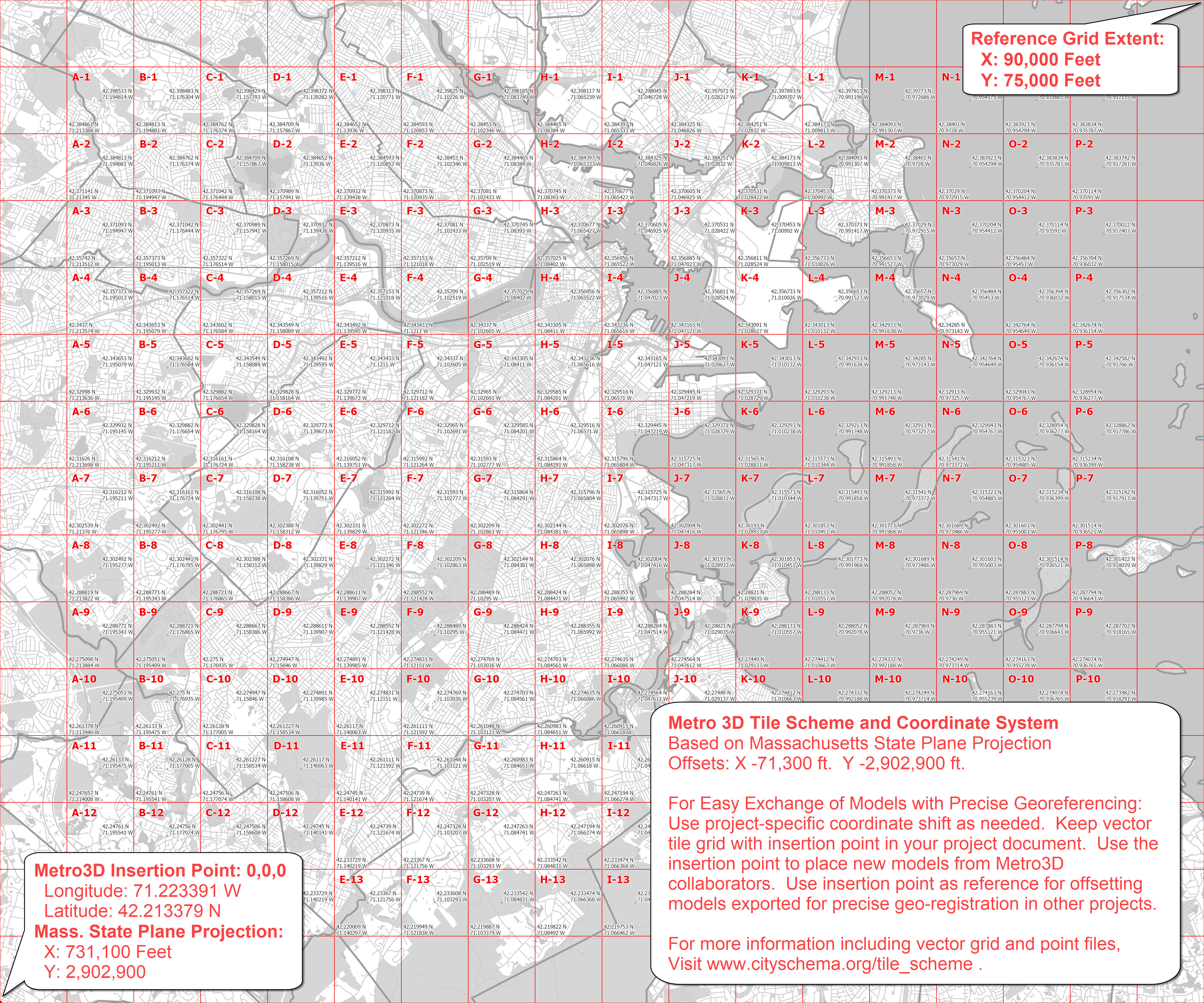
The tiling scheme for the BPDA's 3D model serves as a framework for sharing a detailed model of metropolitan extent with design tools that are limited in terms of spatial extent and file-size. By dividing the city-wide model components into snap-together modules, the tile grid provides a framework for registering model collections and terrain meshes that can be precisely snapped together and draped with a variety tiled groundplan images.
Metro Boston 3D Coordinate System
Surveyors and engineers in Massachusetts prepare their official drawings using the Massachusetts State Plane Coordinate System with coordinates expressed in Feet. The origin of the State Plane grid lies outside the state, which makes coordinate references much larger numbers than most most 3D modeling tools can deal with gracefully. The creators of AutoCAD, 3DsMax, Rhino, SketchUp and Blender all recommend moving geospatially referenced geometry closer to the origin to avoid problems of precision when creating, transforming or rendering.
To facilitate on-going exchange of 3D models, we have chosen a default offset that places the origin to the South-West of Boston and neighboring cities. We expect that modelers will use project-specific coordinate origins. Preserving the Metro3D insertion point and a tile boundary in models will make it easy to make repeat the precise shift precisely geo-located models back and forth between your project and other citySchema collaborators.
Projected Coordinate System: State Plane Massachusetts Mainland (Feet), North American Datum of 1983.
Vertical Datum: North American Vertical Datum, 1988 (NAVD 88) Feet (Height)
Offset To enable exchange precisely located models with diverse applications, State Plane coordinates are offset to keep all coordinates within limits inherent in most 3D design tools.
Coordinate System Origin
- X: 731,100 U.S. MA State Plane Feet
- Y: 2,902,900 U.S. MA State Plane Feet
- Longitude: 71.223391 W
- Latitude: 42.213379 N
- Elevation: 0
- Earth Model: WGS84
- Rotation to align with True North: Clockwise 0.34 Degrees.
OBJ Orientation: Many modeling tools treat the Y axis as vertical. Geographical coordinate systems use a Z-Up, Y-Forward orientation. If you experience mis-orientation when importing OBJ format models into your design projects, check the orientation oprions in your importer. The Z-Up orientation is sometimes obtained by rotating the model -90 degrees arouns the X axis.
SketchUp Geo-Location
To georeference your SketchUp model for interoperability with SketchUp's Geo-Location features, including export of properly located KMZ files:
- Load the SketchUp tile grid and see the latitude and longitude references for tile centers and corners.
- Choose a tile center or corner to be the origin point for your model. This works best for models that are just one or two tiles wide.
- Select all and click your chosen origin point with the Move tool.
- Type [0,0,0] -- which should appear in the Measurement Box (lower right corner of the SketchUp window.) Your model origin should now be at your chosen point.
- Click your origin point with the Rotate tool. and begin a clockwise rotation. Then enter 1.3 (degrees) in the Measurement box. This orients your model to the local Universal Transverse Mercator grid, which SketchUp expects.
- FInally, Go to Model Info > Geolocation and enter the latitude and longitude for your origin point.
- Test your geolocation by trying to add some imagery from File > GeoLocation > Add Imagery
Download Tile Grid Resources
- ArcGIS Projection file for Metro 3D Boston coordinate system.
- Tile reference image in .OBJ format or JPEG (with georefeencing).
- Tile Polygons and Points (including insertion-point and bounding rectangle)
- SketchUp format.
- DXF format Metro Boston 3D coordinate system or Un-shifted State Plane Feet -- useful for registering data layers from unshifted State-Plane data-sets.
- Shapefile format. useful for clipping ground plan images or vector data to precisely register with tiled models.
- GeoJSON format. Helpful for automating processes that involve coordinate transformation of tiled models (see Data Dictionary, below).
- CSV Table format. Provides coordinate information for each tile center in Latitude Longitude or shifter state plane coordinates. Helpful for automating processes that involve coordinate transformation of tiled models (see Data Dictionary, below).
Data Dictionary for Tile Grid Attribute Table
This attribute table is a reference for tile identifiers and tile-center coordinates.
Since the tiles are 5000 feet and square with the State Plane grid, eht state-plane coordinates fom the corners can be calculated by adding or subtracting 2500 feet frm the center coordinate.
| Field Name | Type | Description |
|---|---|---|
Town_Code |
Text |
A three letter abbreviation of the town name. |
Tile_Label |
Text |
a hyphenated label consisting of the letter designating the tile column and the number reflecting the tile row. |
Tile_ID |
Text |
A concatenation of the Town_Code, underscore, and the Tile_Label string. This identifier is used for naming tiled models and folders elminates tile name conflicts for modeling projects that span multiple towns. |
Center_Lat |
Text |
The latitude of the center of the tile. Assuming the WGS84 earth model. |
Center_Lon |
Text |
The longitude of the center of the tile. Assuming the WGS84 earth model. |
BosShift_X |
Text |
The X coordinate of the tile center. Metro Boston 3D coordinate system |
BosShift_Y |
Text |
The Y coordinate of the tile center. Metro Boston 3D coordinate system |
MASP_X |
Text |
The X coordinate of the tile center. Massachusetts State Plane (Mainland, Feet) coordinate system |
MASP_Y |
Text |
The Y coordinate of the tile center. Massachusetts State Plane (Mainland, Feet) coordinate system |